Radios have been around for a long time. Security has not played a very long role within this realm. Consequently, precautions such as CRC, encryption, etc. are not always considered during the transmission of a radio signal. The below tutorial will highlight a replay of a modulated ASK/OOK signal that is non-return-to-zero (NRZ) encoded.
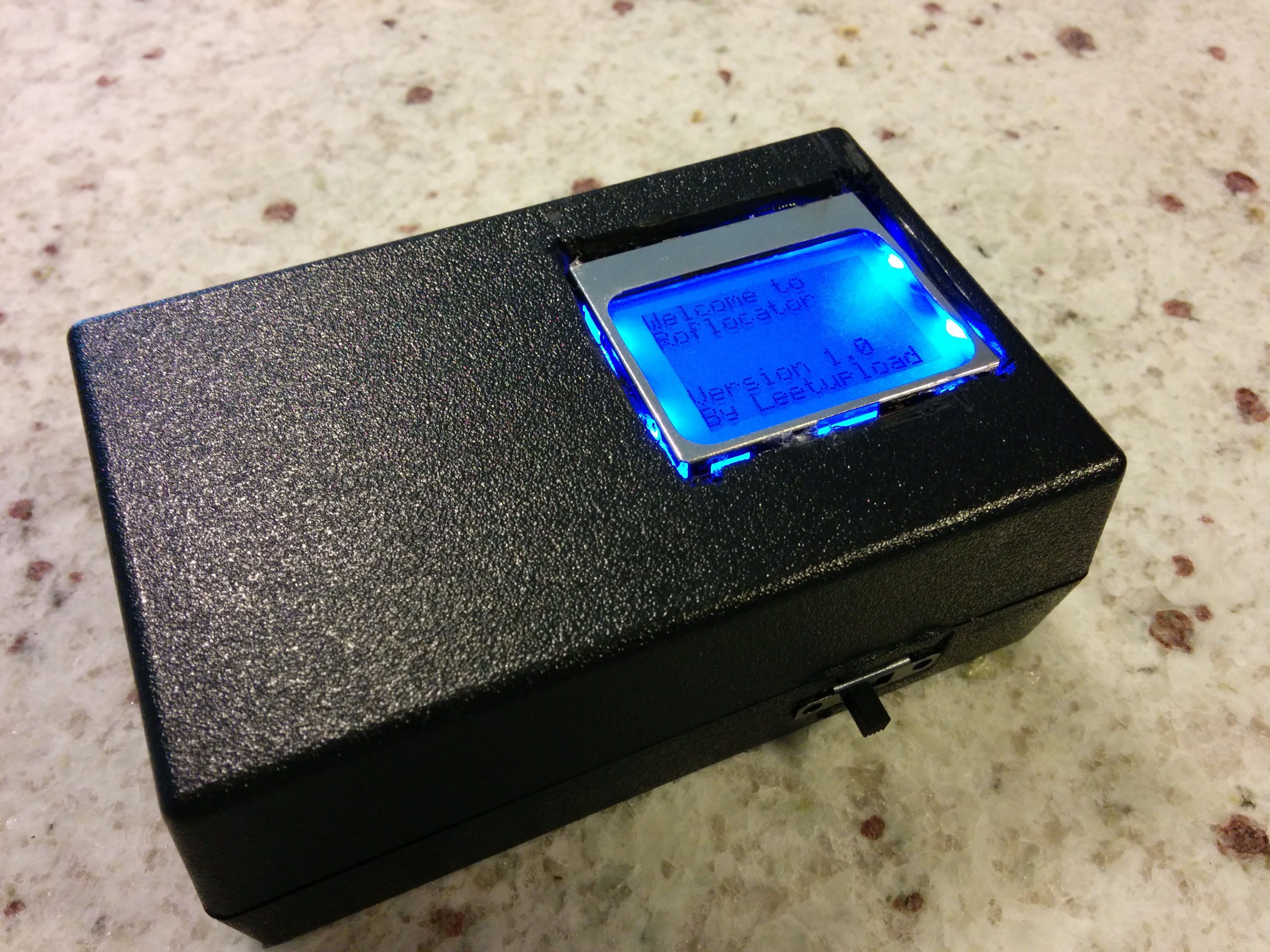
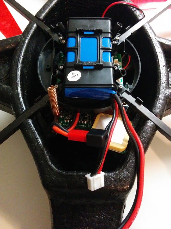
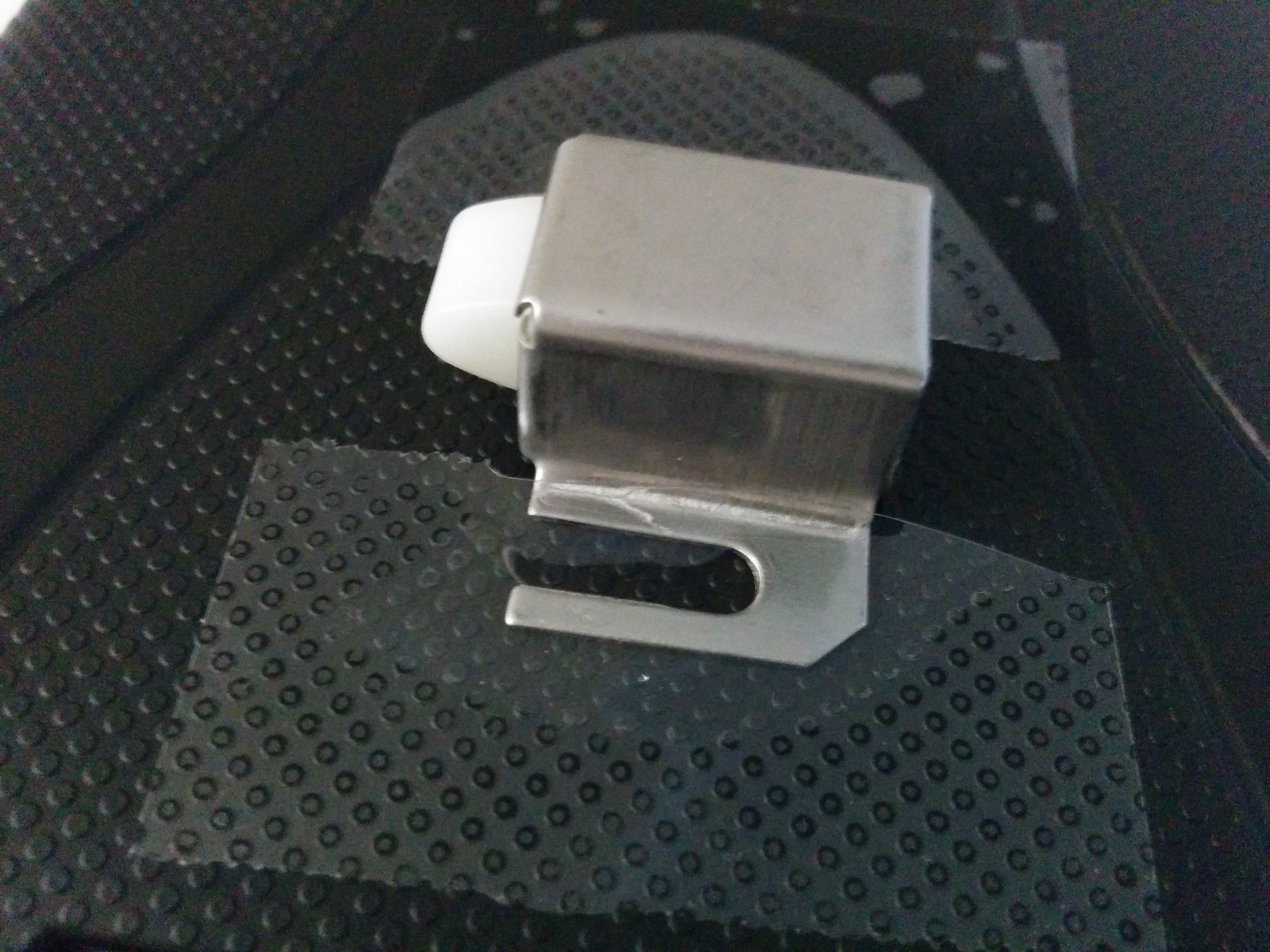
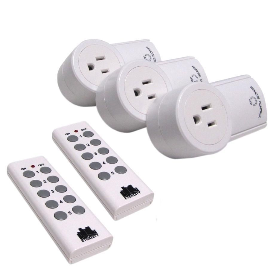
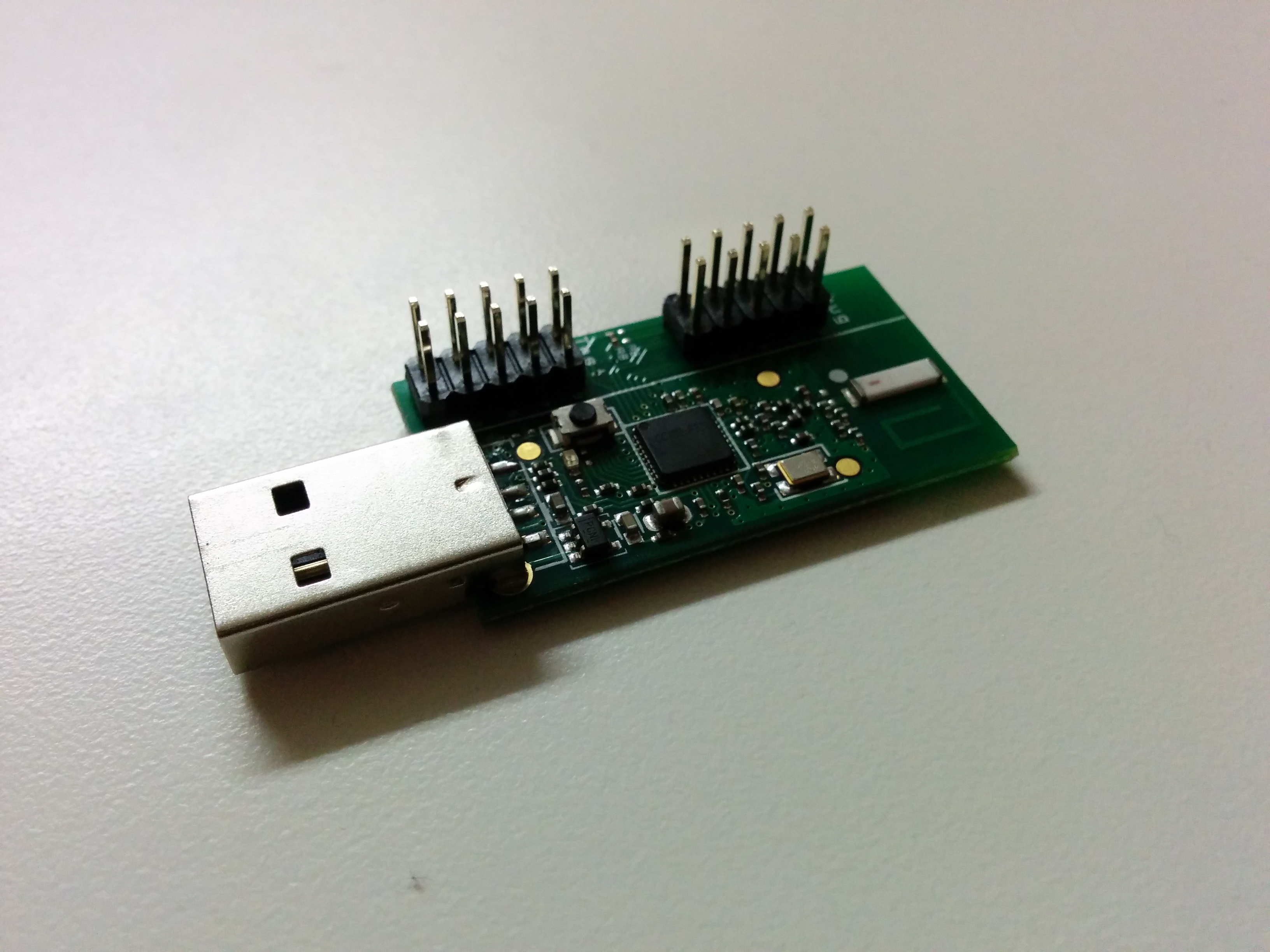
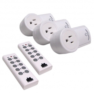
The 433.925MHz band is commonly used across many devices found all over our surroundings. From wireless doorbells to garage door openers, this band is fairly active in our daily lives. The demonstration of replay we will be covering will be wireless RC switches that are common in European households. These devices can be controlled wirelessly to turn on and off any electrical device connected. Naturally, this is an interesting device to investigate. Below is a picture of the device mentioned.
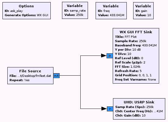
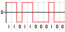
In short, signals are sent as NRZ encoded in the signal as it is sent to the receiver, and subsequently decoded and the function is processed. NRZ line code is binary code where a ‘1’ is represented as a positive voltage and a ‘0’ is represented as a negative voltage. The longer the pulse width, the greater the amount of data. Below is an example of NRZ:
So that we have a more controlled environment and since this is in the US, we will be using an Arduino Uno, an RF link set, and an Arduino ported RC Switch library. This will serve as our example remote controlled RC switch since they are not as common here as they are overseas.
Materials needed:
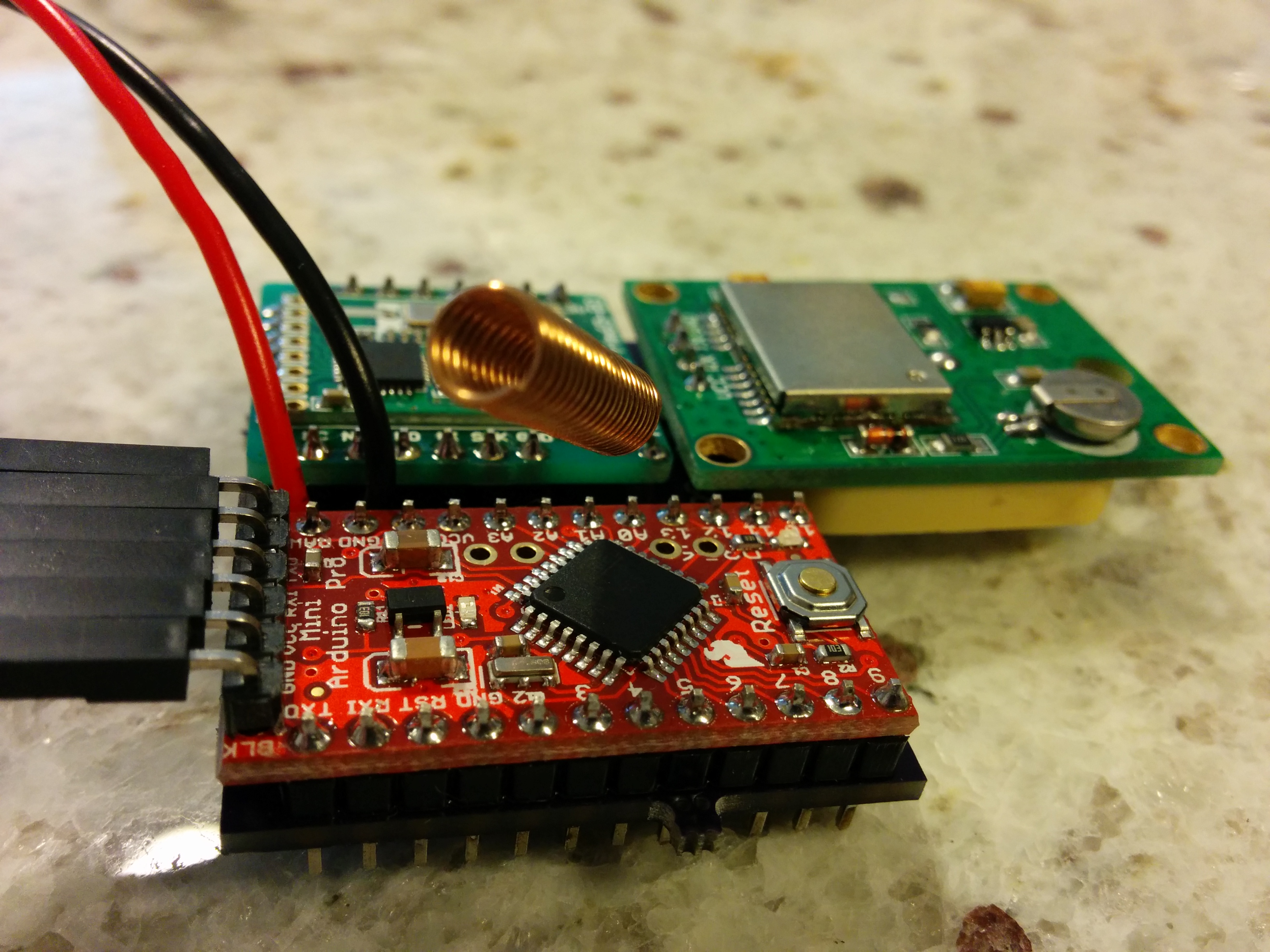
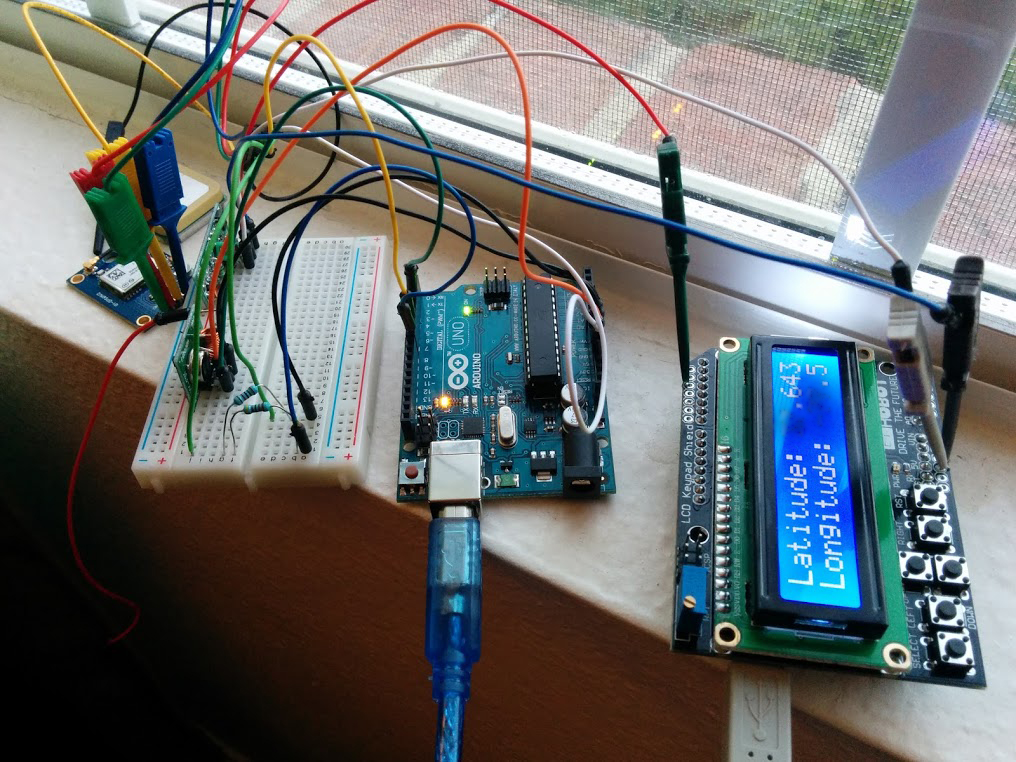
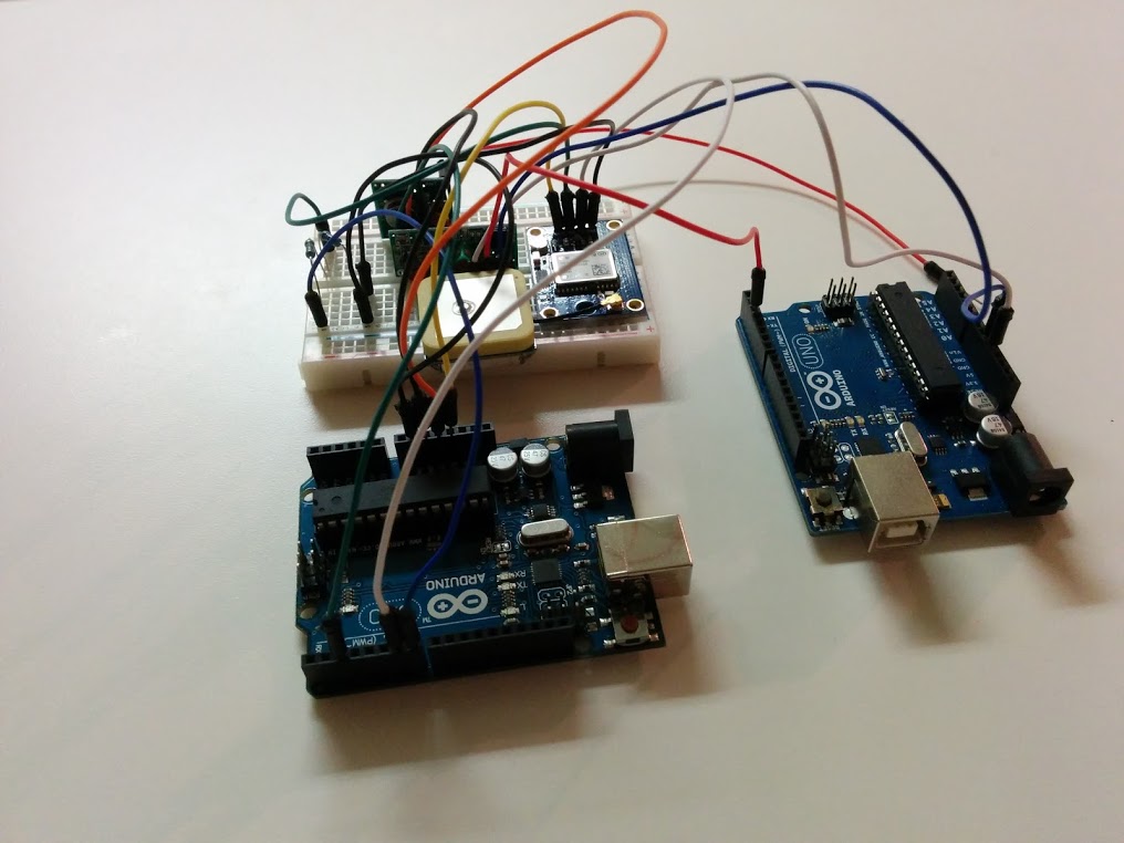
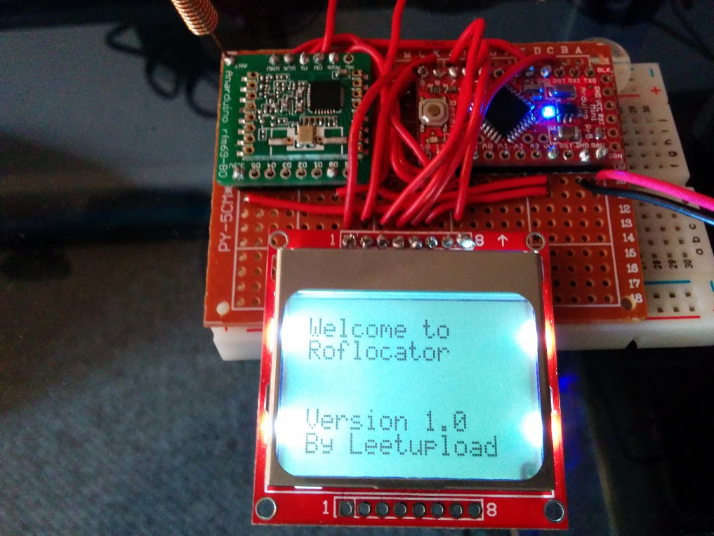
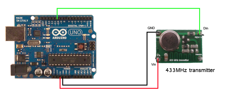
Let’s get started. First, we need to connect and configure our Arduino with the RF Link set and program our microcontroller as a transmitter with the rc-switch library. In the below image is my setup as an example. For my RF 433MHz transmitter (as both the transmitter and receiver tend to vary in pin count and voltage), I have 3 pins on my transmitter: GND, VCC, and DATA. On the breadboard, connect the transmitter directly and connect the appropriate pins — GND to the GND pin on the Arduino, VCC to 5v pin, and DATA to whatever digital pin you choose.
http://rc-switch.googlecode.com/svn/wiki_images/wiring_transmitter.png
With the Arduino physically configured correctly, fire it up and commit the following code (modifying to your pin setup where necessary).
/*
  Simple example for sending

  http://code.google.com/p/rc-switch/
*/

#include <RCSwitch.h>

RCSwitch mySwitch = RCSwitch();

void setup() {
  mySwitch.enableTransmit(2);  // Using Pin #2
}

void loop() {
  mySwitch.send("1100101"); // Send the message 0x65, in ASCII, ‘a’
  delay(1000);  // 1 second delay per transmission; 1000ms
}
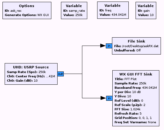
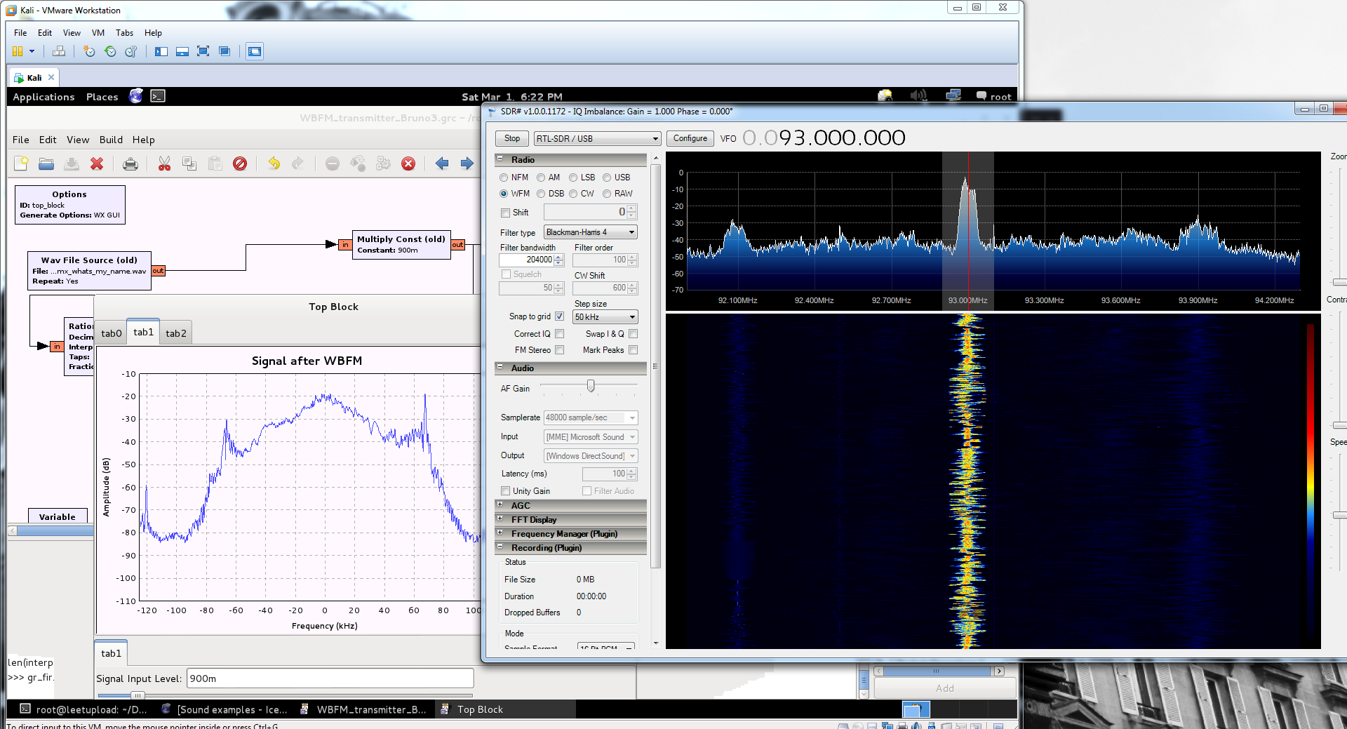
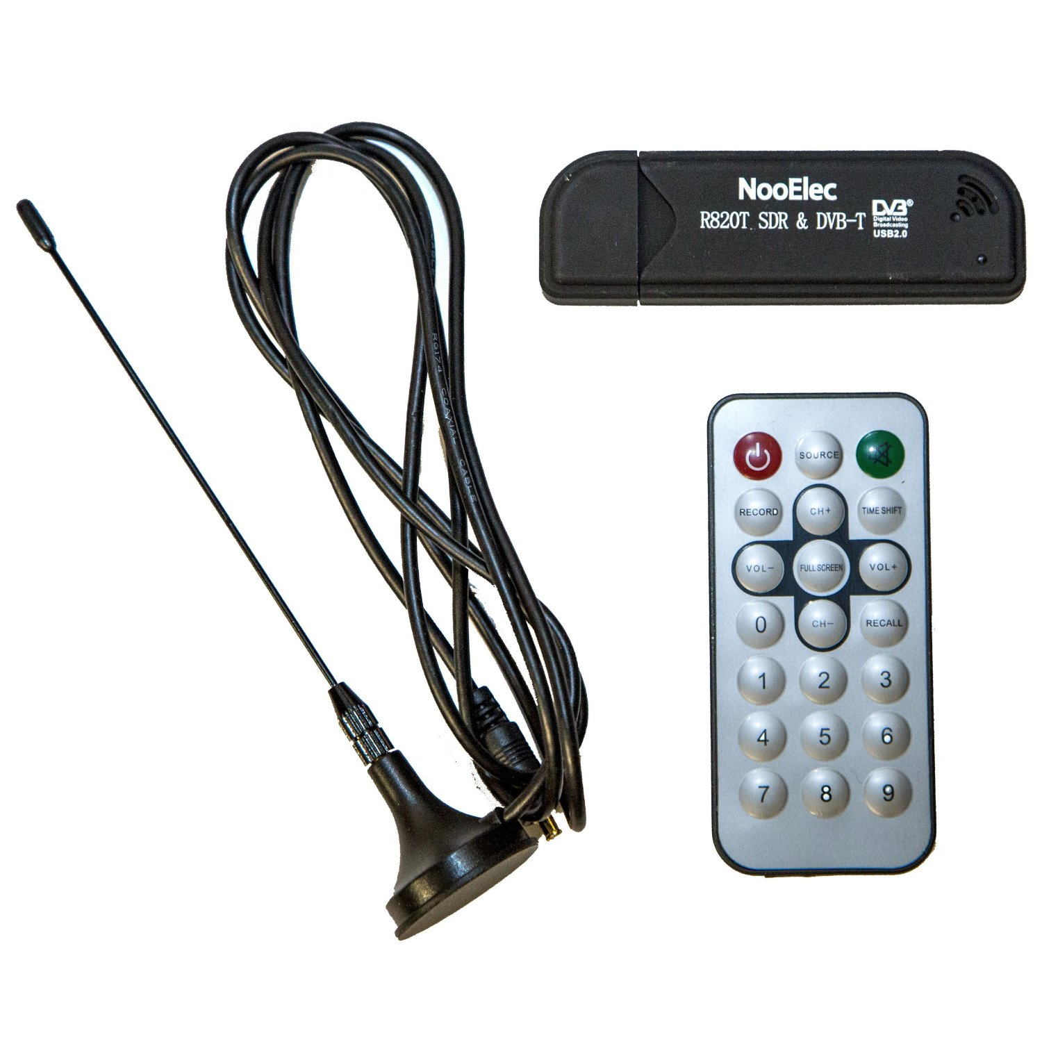
Now that the Arduino is setup, we need to find the signal by using RTL-SDR and SDR-Sharp on our Windows box (you can use gqrx or HDSDR if you are so inclined). Note that the signal generated from the RF link set is not the best. The frequency that it resides on varies at times. However, it should be right around 433 ~ 434MHz. Since this is an AM modulation, select “AM” when listening for the signal.
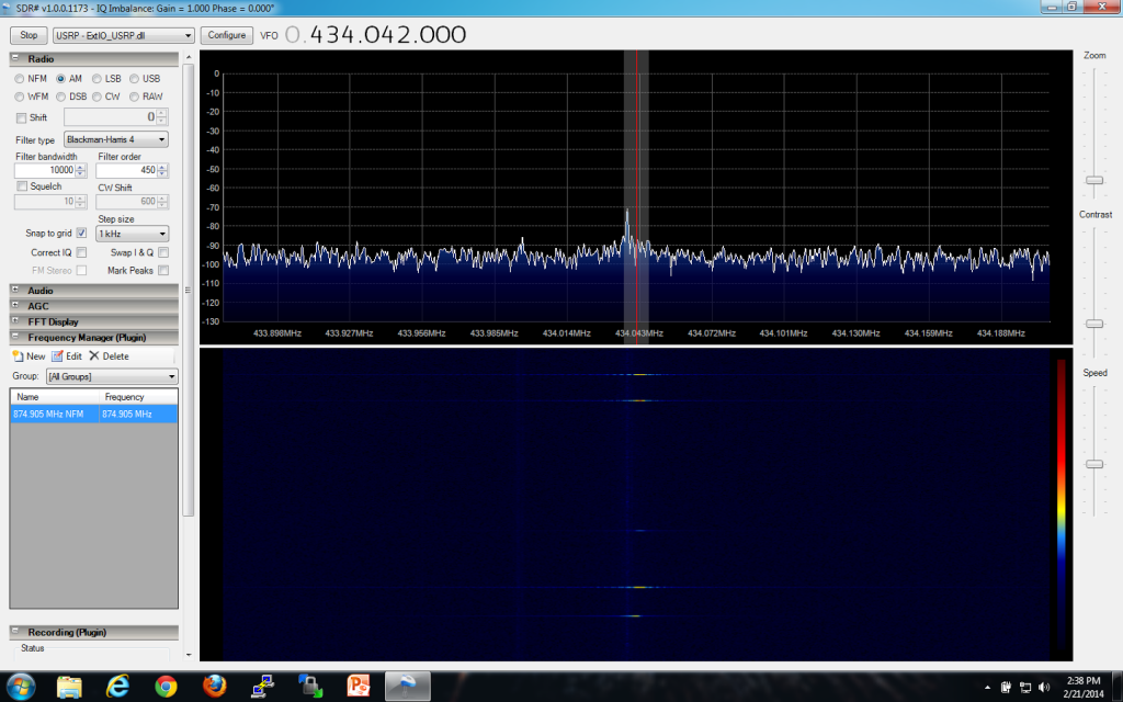
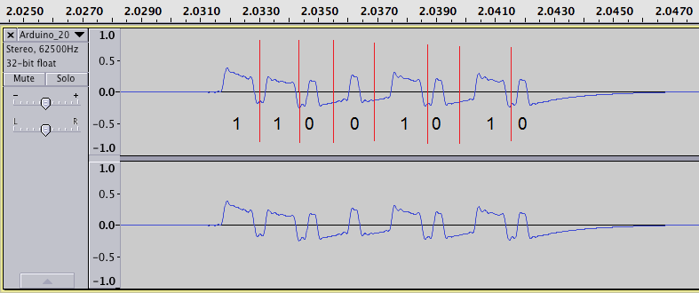
Once you find the signal, record it as a WAV file. Open the signal in Audacity and examine the transmission. As you can see below, it is a fairly straight-forward signal. Without looking at the source code, we can assume the following: it is NRZ encoded, it has been pulse width modulated (PWM), and it is ASK/OOK (Amplitude Shift Keying / On Off Keying — this essentially means with OOK that the carrier is switched on and off in order to convey the presence and absence of data [binary representation]). The last piece of information we need to gleen from the signal is the baud rate. To calculate the baud rate of a signal, follow the steps below:
-
Set the tool at the bottom to length and change the measurement to samples
-
Get the sample rate of the audio (in this case, it is 62,500Hz)
Formula for getting the baud rate:
1 / (samples / samplerate) → 1 / (22 / 62500) = ~2,840bps
Most of the time, this will work, be accurate enough, and serve as one of our variables in our recipe for RFCat.
Given that this signal has been PWM’d, we need to elongate each pulse width to the appropriate length. Unfortunately, most of this takes trial and error. Thankfully, AndrewMac put together the perfect script which addresses these concerns in conjunction with RFCat. With our RFCat dongle in hand, we will be able to transmit our hand-massaged signal which will hopefully be well-received by our Arduino receiver. When dealing with RFCat, we need to define different settings prior to transmitting our data. Given everything we learned earlier about the signal, we need to define the following as such:
d.setMdmModulation(MOD_ASK_OOK)
d.setFreq(frequency)
d.makePktFLEN(keyLen)
d.setMdmDRate(baudRate)
d.setMaxPower()
d.setMdmSyncMode(0)
We first set the modulation to ASK/OOK, set our target frequency to 434042000Hz (433.925MHz), essentially define how long our message is, set the baud rate to 2840bps, ensure that the transmission is set to full power, and to disable any preamble or syncwords, set Sync Mode to 0.
With the assumption that you have a somewhat solid understanding of RFCat (from previous articles) as well as python, the below script will help us execute the above with the necessary padding and PWM adjustment such that we receive a matching transmission.
/*
Script by AndrewMac of andrewmohawk.com
*/
#!/usr/bin/env python
import sys
import time
from rflib import *
from struct import *
import argparse
import pprint
import bitstring
keyLen = 0
baudRate = (1 / 0.000350) #because the pulse width is 350 in the code
frequency = 434042000
repeatNum = 30
def ConfigureD(d):
d.setMdmModulation(MOD_ASK_OOK)
d.setFreq(frequency)
d.makePktFLEN(keyLen)
d.setMdmDRate(baudRate)
d.setMaxPower()
d.setMdmSyncMode(0)
print "[+] Radio Config:"
print " [-] ---------------------------------"
print " [-] MDMModulation: MOD_ASK_OOK"
print " [-] Frequency: ",frequency
print " [-] Packet Length:",keyLen
print " [-] Baud Rate:",baudRate
print "[-] ---------------------------------"
#raw what we are sending
bin_str_key = "1100101";
#adjust the key to make it longer so that the pulse width is correct
long_bin_key = "";
for k in bin_str_key:
x = "*"
if(k == "1"):
x = "11100" # <mossmann> A zero is encoded as a longer high pulse (high-high-low)
if(k == "0"):
x = "1000" #<mossmann> and a one is encoded as a shorter high pulse (high-low-low).
long_bin_key = long_bin_key + x
print "[+] Binary (PWM) key:\n\t",long_bin_key,"\n"
padAmount = len(long_bin_key) % 8
for x in range(0,8-padAmount):
long_bin_key = "0" + long_bin_key
print "[+] Binary Padded (PWM) key:\n\t",long_bin_key,"\n"
key_packed = bitstring.BitArray(bin=long_bin_key).tobytes()
keyLen = len(key_packed)
print "[+] Key len:\n\t",keyLen,"\n"
print "[+] Key:\n\t", key_packed.encode('hex'),"\n"
print ""
d = RfCat()
ConfigureD(d)
print "[%] Transmitting key: ",repeatNum," times\n"
#startString = "11101";
startStringBin = "000000000000000" + "1000100010001000111001000"
startkey_packed = bitstring.BitArray(bin=startStringBin).tobytes()
d.RFxmit(startkey_packed)
d.makePktFLEN(keyLen)
for i in range(0,repeatNum):
sys.stdout.write( "." )
d.RFxmit(key_packed)
#endString = "011";
d.RFxmit('\xFF')
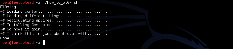
sys.stdout.write("Done.\n")
To briefly explain what the code is doing, we are taking our pre-defined settings such as modulation, baud rate, etc. and applying it to our RFCat configuration. We then take our key that we wish to send (already dissected from the Audacity screenshot taken above) and assign it to the variable bin_str_key. We then alter the key so that all ‘1’s are 11100 (high-high-low) and the ‘0’s are 1000 (high-low-low). Our original key (1100101) is now mutated into a new binary PWM key which now appears as 11100111001000100011100100011100. Our pulse width is now accurate. The next step is to pad the binary PWM key, convert it to bytes (so that the data is not sent out as ASCII), and then take the length of the now-in-byte format binary PWM padded key in order to set d.makePktFLEN(keyLen) so that RFCat has a fixed key length when sending the data. Now that the beef of our information has been created, we now need to create the start and end bits so that our Arduino program knows when our data transmission begins and when it ends. After all of this is defined, we then execute the following RFxmit() functions in order: d.RFxmit(startkey_packed), d.RFxmit(key_packed), and d.RFxmit(‘\xFF’). The end transmission appears as: 00000000000000010001000100010001110010001110011100100010001110010001110011111111
This message is then sent ~30 times given that our receiver is a bit finicky, and that it is a requirement for the signal to be sent 10 times to be considered a complete message (as per the rc-switch source code). However, to check and make sure that the signal was originally sent correctly, modify repeatNum to equal ‘1’, re-record the signal in SDR-Sharp, and line-up the result against the originally recorded Arduino frequency. It should look virtually the same.
Take your Arduino and use the following code to receive:
/*
  Simple example for receiving

  http://code.google.com/p/rc-switch/
*/

#include <RCSwitch.h>

RCSwitch mySwitch = RCSwitch();

void setup() {
  Serial.begin(9600);
  mySwitch.enableReceive(0);  // Receiver on interrupt 0 => that is pin #2
}

void loop() {
  if (mySwitch.available()) {

    int value = mySwitch.getReceivedValue();

    if (value == 0) {
      Serial.print("Unknown encoding");
    } else {
      Serial.print("Received ");
      Serial.print( mySwitch.getReceivedValue() );
      Serial.print(" / ");
      Serial.print( mySwitch.getReceivedBitlength() );
      Serial.print("bit ");
      Serial.print("Protocol: ");
      Serial.println( mySwitch.getReceivedProtocol() );
    }

    mySwitch.resetAvailable();
  }
}
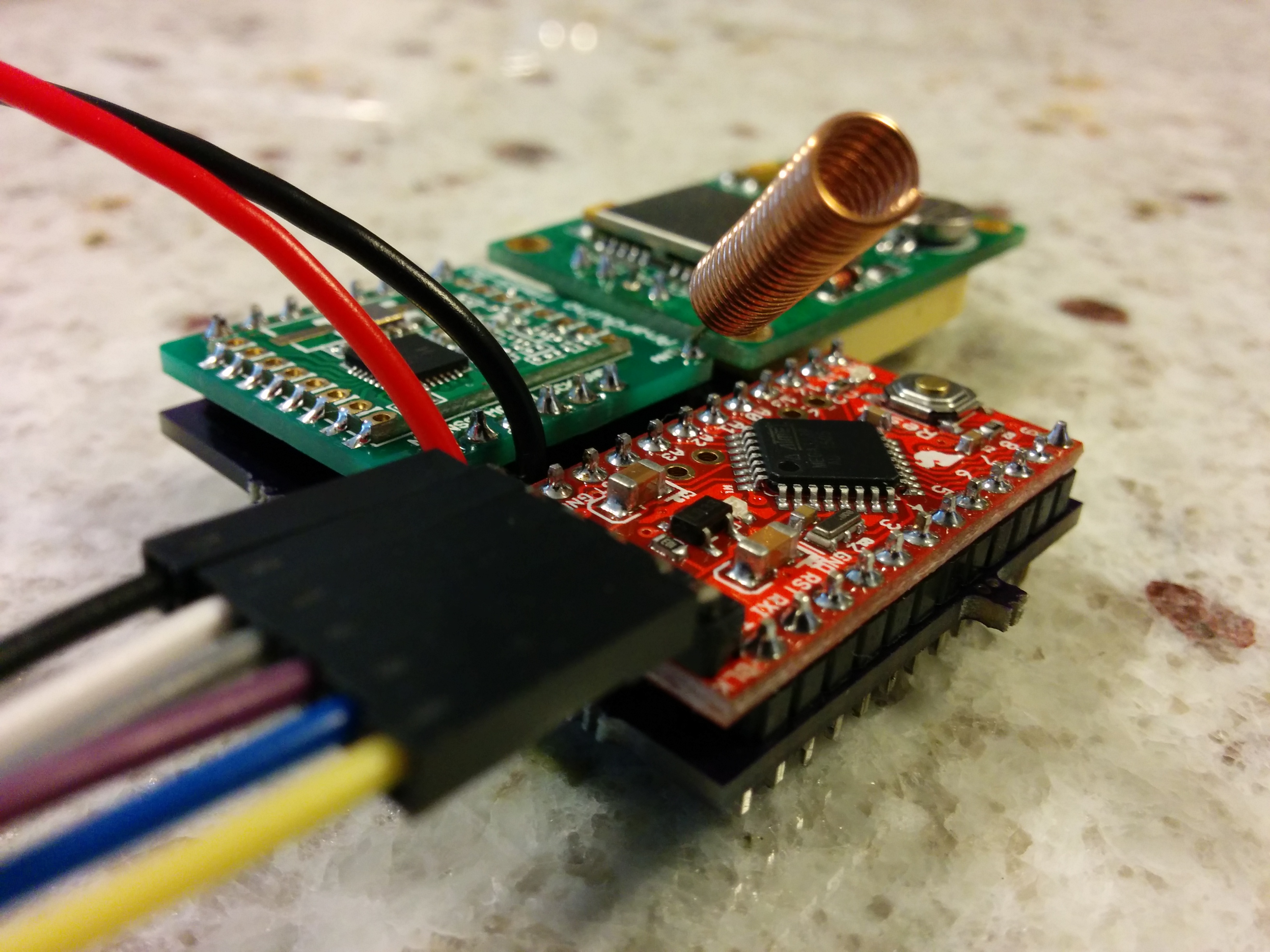
Thereafter, configure the receiver component you have and wire it identically as you already have on the Arduino, except rearrange the order of the wires. With my receiving component my pin order from right to left is: GND, DATA, DATA, VCC. In my setup, I only use the first data pin. The below diagram may be of use.
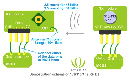
http://seeedstudio.com/wiki/images/0/0f/315433RF.jpg
Assuming that your signal matches up, go ahead and run the script with a higher repetition than 1 iteration, such as 30+. With any luck, your signal should have been successfully replayed!